| Data
sheets |
|
tt back to Table of contents |
| Series 498 |
| Design 0.01
with length compensation, tubular design
0.03 without length compensation, tubular design
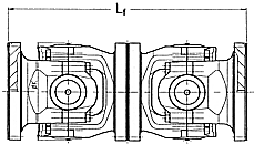
9.04 without length compensation, double flange shaft
design |
|
0.01 |

|
| |
| |
 |
|
 |
|
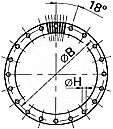
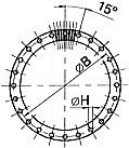
Flange connection with
Hirth-serration
Each shaft size has a specific hole
pattern
(see table).
Other hole patterns on request. |
| |
20-hole
flange |
|
24-hole
flange |
|
|
|
| 0.03 |

|
| 9.04 |

|
|
| |
Series 498.00-.15
|
Shaft size |
498.00 |
498.05 |
498.10 |
498.15 |
|
TCS |
kNm |
1880 |
1620 |
1430 |
2340 |
2080 |
1750 |
3000 |
2600 |
2200 |
3640 |
3100 |
2700 |
|
TK |
kNm |
1450 |
1250 |
1100 |
1800 |
1600 |
1350 |
2300 |
2000 |
1700 |
2800 |
2400 |
2100 |
|
TDW |
kNm |
900 |
780 |
680 |
1120 |
1000 |
840 |
1430 |
1250 |
1050 |
1750 |
1500 |
1300 |
|
LC |
- |
0,098
x 10 |
0,115
x 10 |
0,144
x 10 |
0,202
x 10 |
0,224
x 10 |
0,322
x 10 |
0,381
x 10 |
0,530
x 10 |
0,684
x 10 |
0,903
x 10 |
1,09
x 10 |
1,35
x 10
|
|
Deflection angle |
ß |
 ° ° |
5 |
10 |
15 |
5 |
10 |
15 |
5 |
10 |
15 |
5 |
10 |
15 |
|
Flange-ø |
A |
mm |
600 |
650 |
700 |
750 |
|
Rotation-ø |
K |
mm |
600 |
650 |
700 |
750 |
| |
B 1) |
mm |
555 |
605 |
655 |
695 |
|
G |
mm |
75 |
80 |
90 |
95 |
|
H 2) |
mm |
25 |
25 |
25 |
31 |
|
I 3) |
- |
20 |
20 |
24 |
24 |
|
M |
mm |
370 |
370 |
370 |
390 |
390 |
410 |
420 |
420 |
440 |
460 |
460 |
480 | |
Series
498.20-.35
|
Shaft size |
498.20 |
498.25 |
498.30 |
498.35 |
|
TCS |
kNm |
4420 |
3800 |
3300 |
5300 |
4500 |
4050 |
6300 |
5400 |
4700 |
7400 |
6500 |
5600 |
|
TK |
kNm |
3400 |
2950 |
2600 |
4100 |
3500 |
3100 |
4900 |
4200 |
3600 |
5700 |
5000 |
4300 |
|
TDW |
kNm |
2120 |
1850 |
1600 |
2550 |
2200 |
1950 |
3050 |
2650 |
2250 |
3500 |
3100 |
2700 |
|
LC |
- |
1,29
x 10 |
1,69
x 10 |
2,14
x 10 |
2,05
x 10 |
3,05
x 10 |
3,48
x 10 |
3,79
x 10 |
5,65
x 10 |
7,04
x 10 |
6,46
x 10 |
9,71
x 10 |
10,7
x 10
|
|
Deflection angle |
ß |
 ° ° |
5 |
10 |
15 |
5 |
10 |
15 |
5 |
10 |
15 |
5 |
10 |
15 |
|
Flange-ø |
A |
mm |
800 |
850 |
900 |
950 |
|
Rotation-ø |
K |
mm |
800 |
850 |
900 |
950 |
| |
B 1) |
mm |
745 |
785 |
835 |
885 |
|
G |
mm |
100 |
105 |
110 |
120 |
|
H 2) |
mm |
31 |
38 |
38 |
38 |
|
I 3) |
- |
24 |
24 |
24 |
24 |
|
M |
mm |
480 |
480 |
500 |
530 |
530 |
555 |
555 |
555 |
580 |
580 |
580 |
610 | |
Series
498.40-.60
|
Shaft size |
498.40 |
498.45 |
498.50 |
498.55 |
498.60 |
|
TCS |
kNm |
8700 |
7500 |
6500 |
10000 |
8700 |
7500 |
11500 |
10000 |
8600 |
13200 |
11400 |
9900 |
15000 |
13000 |
11200 |
|
TK |
kNm |
6700 |
5800 |
5000 |
7700 |
6700 |
5800 |
8900 |
7700 |
6600 |
10200 |
8800 |
7600 |
11500 |
10000 |
8600 |
|
TDW |
kNm |
4200 |
3600 |
3100 |
4800 |
4200 |
3600 |
5500 |
4800 |
4100 |
6300 |
5500 |
4700 |
7200 |
6200 |
5400 |
|
LC |
- |
11,7
x 10 |
16,1
x 10 |
17,4
x 10 |
15,5
x 10 |
21,9
x 10 |
28,71
x 10 |
23,9
x 10 |
35
x 10 |
42,63
x 10 |
41,6
x 10 |
56,3
x 10 |
70,8
x 10 |
60,9
x 10 |
89,9
x 10 |
102
x 10
|
|
Deflection angle |
ß |
 ° ° |
5 |
10 |
15 |
5 |
10 |
15 |
5 |
10 |
15 |
5 |
10 |
15 |
5 |
10 |
15 |
|
Flange-ø |
A |
mm |
1000 |
1050 |
1100 |
1150 |
1200 |
|
Rotation-ø |
K |
mm |
1000 |
1050 |
1100 |
1150 |
1200 |
| |
B 1) |
mm |
925 |
975 |
1025 |
1065 |
1115 |
|
G |
mm |
125 |
130 |
135 |
140 |
150 |
|
H 2) |
mm |
42 |
42 |
42 |
50 |
50 |
|
I 3) |
- |
20 |
20 |
20 |
20 |
20 |
|
M |
mm |
625 |
625 |
655 |
645 |
645 |
675 |
670 |
670 |
700 |
715 |
715 |
745 |
740 |
740 |
775 | |
TCS
TK
TDW
Lc

* |
Functional limit
torque *
Catalogue torque *
Fatigue torque *
Bearing
capacity factor *
Explanations see
Selection of cardan shafts | |
ß = max. deflection
angle per joint
Flange bolt connections are also supplied on
request.
For summary see
Flange boltings
Intermediate sizes avalable
on request |
1) Tolerance +- 0,1
mm
2) Tolerance + 0,2 mm
3) Number of flange holes
| |
Length dimensions (Lz/Lf) of the range 0.01 * 0.03 * 9.04 on
request |
|
tt back to Table of contents |
![]()
![]()
![]() DANA
Industrial Drive Shafts Catalogue
DANA
Industrial Drive Shafts Catalogue