|
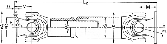
Shaft size |
687.15 |
687.20 |
687.25 |
687.30 |
687.35 |
687.40 |
|
TCS |
kNm |
2,4 |
3,5 |
5 |
6,5 |
10 |
14 |
|
TK |
KNm |
1,8 |
2,7 |
3,8 |
5,0 |
7,7 |
10,5 |
|
TDW |
KNm |
0,7 |
1,0 |
1,6 |
1,9 |
2,9 |
4,4 |
|
LC |
- |
1,79
x 10 |
5,39
x 10 |
1,79
x 10 |
2,59
x 10 |
0,0128 |
0,0422 |
|
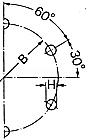
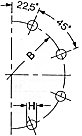
Deflection angle |
ß |
 ° ° |
25 |
25 |
25 |
25 |
25 |
25 |
44 |
25 |
44 |
|
Flange-ø *** |
A |
mm |
100** |
120 |
120** |
120** |
150 |
150** |
180 |
150** |
150** |
180 |
180 |
|
Rotation-ø |
K |
mm |
90 |
98 |
113 |
127 |
127 |
144 |
144 |
160 |
160 |
160 |
160 |
| |
B 1) |
mm |
84 |
101,5 |
101,5 |
101,5 |
130 |
130 |
155,5 |
130 |
130 |
155,5 |
155,5 |
|
C 2) |
mm |
57 |
75 |
75 |
75 |
90 |
90 |
110 |
90 |
90 |
110 |
110 |
|
F 3) |
mm |
2,5 |
2,5 |
2,5 |
2,5 |
3 |
3 |
3 |
3 |
3 |
3 |
3 |
|
G |
mm |
7 |
8 |
8 |
8 |
10 |
10 |
12 |
10 |
10 |
12 |
12 |
|
H 4) |
mm |
8,25 |
10,25 |
10,25 |
10,25 |
12,25 |
12,1 |
14,1 |
12,1 |
12,1 |
14,1 |
14,1 |
|
I 5) |
- |
6 |
8 |
8 |
8 |
8 |
8 |
8 |
8 |
8 |
8 |
8 |
|
M |
mm |
48 |
54 |
70 |
72 |
78 |
95 |
90 |
102 |
102 |
102 |
102 |
|
S |
mm |
63,5 x 2,4 |
76,2 x 2,4 |
89 x 2,4 |
90 x 3 |
100 x 3 |
100 x 3 |
120 x 3 |
100 x 4,5 |
120 x 3 |
100 x 4,5 |
|
W 7) |
- |
36 x 1,5 |
40 x 1,5 |
45 x 1,5 |
48 x 1,5 |
54 x 1,5 |
54 x 1,5 |
62 x 1,75 | |
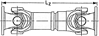
Length dimensions * weights * moments of
inertia * torsional stiffness
|
Design |
Shaft size |
687.15 |
687.20 |
687.25 |
687.30 |
687.35 |
687.40 |
|
0.02 |
Lz min |
mm |
346 |
379 |
458 |
492 |
504 |
582 |
572 |
586 |
693 |
586 |
693 |
|
La |
mm |
60 |
70 |
100 |
110 |
110 |
110 |
110 |
110 |
180 |
110 |
180 |
|
G |
kg |
5,7 |
8,4 |
12,0 |
13,0 |
14,2 |
24,0 |
25,6 |
28,7 |
30,3 |
29,4 |
30,9 |
|
Gr |
kg |
3,62 |
4,37 |
5,13 |
6,44 |
6,44 |
7,18 |
7,18 |
8,66 |
10,6 |
8,66 |
10,6 |
|
Jm |
kgm² |
0,0043 |
0,0089 |
0,0144 |
0,0245 |
0,0245 |
0,043 |
|
0,0676 |
0,0706 |
0,0776 |
0,0806 |
|
JmR |
kgm² |
0,0034 |
0,0059 |
0,0096 |
0,0122 |
0,0122 |
0,0169 |
0,0169 |
0,0296 |
0,0242 |
0,0296 |
0,0242 |
|
C |
Nm/rad. |
0,26 x
10 |
0,42
x 10 |
0,71
x 10 |
0,78
x 10 |
0,78
x 10 |
1,18
x 10 |
|
2,17
x 10 |
1,61
x 10 |
2,17
x 10 |
1,61
x 10 |
|
CR |
Nm/rad. |
0,34
x 10 |
0,60
x 10 |
0,98
x 10 |
1,25
x 10 |
1,25
x 10 |
1,72
x 10 |
1,72
x 10 |
3,02
x 10 |
2,47
x 10 |
3,02
x 10 |
2,47
x 10 |
|
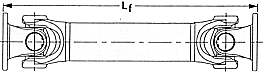
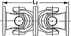
0.03 |
Lf min |
mm |
221 |
239 |
282 |
310 |
322 |
379 |
369 |
423 |
449 |
423 |
449 |
|
G |
kg |
4,1 |
508 |
8,6 |
8,6 |
9,8 |
18,0 |
19,6 |
22,8 |
21,0 |
23,4 |
21,6 |
|
Jm |
kgm² |
0,0038 |
0,0085 |
0,0129 |
0,0238 |
0,0238 |
0,04 |
|
0,066 |
0,0628 |
0,076 |
0,0728 |
|
C |
Nm/rad. |
0,44
x 10 |
0,86
x 10 |
1,44
x 10 |
1,47
x 10 |
1,47
x 10 |
1,81
x 10 |
|
3,35
x 10 |
2,78
x 10 |
3,35
x 10 |
2,78
x 10 |
|
9.01 |
Lz min |
mm |
296 |
322 |
361 |
379 |
391 |
510 |
500 |
505 |
525 |
505 |
525 |
|
La min |
mm |
38 |
41 |
36 |
36 |
36 |
70 |
70 |
70 |
60 |
70 |
60 |
|
Lz max |
mm |
348 |
381 |
425 |
453 |
465 |
550 |
540 |
545 |
645 |
545 |
645 |
|
La max |
mm |
90 |
100 |
100 |
110 |
110 |
110 |
110 |
110 |
180 |
110 |
180 |
|
9.03 |
Lz min |
mm |
245 |
274 |
313 |
331 |
343 |
424 |
414 |
446 |
- |
446 |
- |
|
La min |
mm |
25 |
27 |
28 |
29 |
29 |
50 |
50 |
50 |
- |
50 |
- |
|
Lz max |
mm |
280 |
317 |
355 |
397 |
409 |
484 |
474 |
506 |
- |
506 |
- |
|
La max |
mm |
60 |
70 |
70 |
95 |
95 |
110 |
110 |
110 |
- |
110 |
- |
|
9.04 |
Lf min |
mm |
192 |
216 |
240 |
288 |
312 |
380 |
360 |
408 |
408 |
408 |
408 |
|
| |