![]()
![]()
![]() DANA
Industrial Drive Shafts Catalogue
DANA
Industrial Drive Shafts Catalogue
| Drive Shafts | |
|
|
| Technical directions for application | ||||
| tt back to Table of contents | ||||
| Operating angles The most common arrangements are the Z- and W-deflections. To begin with, we will consider the system in which the shafts to be connected are in the same plane. Z-arrangement 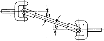 W-arrangement 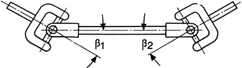 Maximum permissible angle difference The condition The deflection angles for high-torque and high-speed machine drives should be equal. If not, the difference should be limited 1° - 1,5°. Greater differences about 3° to 5° are acceptable without disadvantages in low speed applications. For applications with varying deflection conditions it is important to obtain uniformity, if possible over the complete deflection range. Deflection in two planes means that the deflection is both horizontal and vertical. The combination of two identical types of deflection (Z/Z or W/W) and identical deflection angles ensure uniformity. For combination of Z- and W deflection the inner yokes must be offset. Please consult DANA's application engineers to determine the proper amount of angular offsct. Determination of the maximum permissible operating deflection angle β Depending on the cardan shaft series the maximum deflection angle per jomt is β = 5° - 44°. Due to the kinematic conditions of the cardan joint as described before, the deflection angle must be limited in relation to the speed. Calculations and observations of many applications have shown that certain mass acceleration torques of the centre part must not be exceeded in order to guarantee smooth running of the drive systems. This acceleration torque depends on the
|
||||
| tt back to Table of contents | ||||
| Email : info@landmark-autoparts.com | Websites |
|