![]()
![]()
![]() DANA
Industrial Drive Shafts Catalogue
DANA
Industrial Drive Shafts Catalogue
| Drive Shafts | |
|
|
| General fundamental theory | ||
| tt back to Table of contents | ||
| Kinematics of Hooke's joints
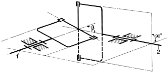
1. The joints In the theory of mechanics the cardan joint or Hooke's joint is defined as a spatial or spherical drive unit with a non-uni form gear ratio or transmission. The transmission behaviour of this joint is described by the equation. |
||
 |
||
In this equation |
||
 |
||
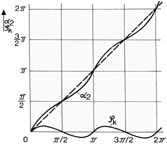
| A measure for the non-uniformity is the
difference of the rotation angles
|
||
|
Expressed by an equation, that means:
|
(also called gimbal error)  b) Gear ratio |
|
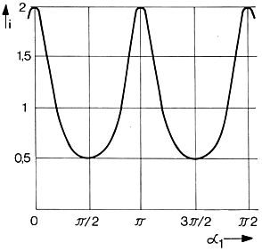
The following diagram shows the gear ratio i = |
 |
|
|
The degree of non-uniformity U is
defined by: U = i max. - i min. = tan β * sin β where:  |
||
 |
||
|
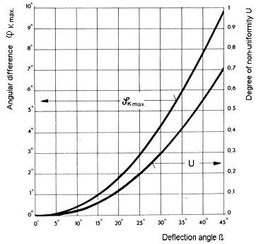
The diagram shows the course of the
degree of nonuniformity U and of the angular difference
From the motion equation it is evident that a homokinematic motion behaviour corresponding to the dotted line under 45° - as shown in the diagram - can only be obtained for the deflection angle β = 0°. A synchronous or homokinematic running can be achieved by a suitable combination or connection of two or more joints. |
||
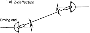
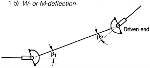
| 2. The universal shaft The rotation angle difference 1) The deflection angles of both joints must be equal, i.e. Two arrangements are possible: |
||
 |
||
 |
||
| 2) The two joints must have a kinematic
angular relationship of 90° ( For a more intensive study of universal shaft kinematics we refer you to the VDI-recommendation 2722 to the relevant technical literature. |
||
| tt back to Table of contents | ||
| Email : info@landmark-autoparts.com | Websites |
|