lnfluence
of speed and deflection angle
Speed
The permissible speed of the universal joint shaft is
influenced by the following parameters:
 size of the shaft size of the shaft
 widening of the yokes due to centrifugal
force widening of the yokes due to centrifugal
force
 quality of balancing quality of balancing
 true running of the connected flanges true running of the connected flanges
 deflection angle during operation deflection angle during operation
 length of the shaft length of the shaft
Speed x deflection angle
Theoretical considerations and observations of various
applications have shown that certain mass acceleration
moments of the centre part of the shaft must not be
exceeded if a quiet running of the shaft drives is to be
achieved. This mass acceleration moment depends on the
speed n, the deflection angle β and the mass moment of
inertia of the centre part of the shaft.
The mechanically possible deflection angle for each joint
depends on the size of the shaft. Owing to the kinematic
conditions of the universal joint described before, the
practical deflection angle must be limited in relation to
the rotational speed.
The following table shows the max. speeds and the max.
permissible values for the product
 of the various shaft sizes for a moment of
inertia of the centre part according to a shaft length of
approx. 1500 mm. of the various shaft sizes for a moment of
inertia of the centre part according to a shaft length of
approx. 1500 mm.
When approaching the critical rotational speed and in the
light of the demand of maintenance of balance quality (see Balancing of Propeller shafts ) , it may be necessary to reduce
the rotational speed.
Joint size
|
n max.
[1/min.]
|
(n x β) perm.
[°/min.]
|
2015
2020
2025
2030
2035
2040
2045
2047
2050
2055
2060
2065
|
6 000
6 000
6 000
6 000
5 600
5 000
4 700
4 500
4 500
4 500
4 100
3 900
|
27 000
26 000
24 000
22 000
21 000
20 000
19 000
19 000
19 000
18 000
17 000
17 000
|
Since the quiet running of the universal shaft in
practice also largely depends on the installation
conditions, the n x β values shown in the table can only
be regarded as a guidance. Slightly higher values are
possible. In case of favourable spring and mass
conditions the values may be exceeded by up to 50 %.
Transverse whirling speed
Universal shafts are flexible elastic units, which must
be calculated considering the bending vibrations and the
transverse whirling speed.
For reasons of safety the max. perm. operating speed must
be sufficiently below the transverse whirling speed.
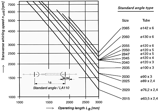
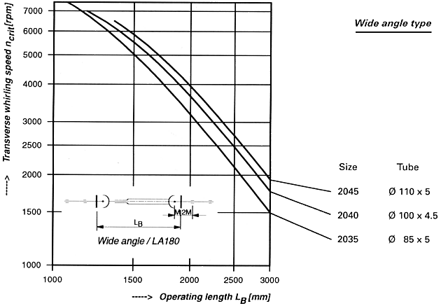
The diagram on the end of this page shows the transverse
whirling speeds of the varbus shaft sizes
depending on the operating lengths and the tube
dimensions shown in the catalogue.
The diagram values apply to normal installation
conditions with a supposed distance of the centre point
of the joint shaft from the adjacent bearing equal to 3 x
M and a rigid suspension of the connected units.
In order to achieve a safe and quiet running behaviour
the max. perm. operating speed, i.e. including a possible
excess speed, must not exceed 80 % of the transverse
whirling speed shown in the diagram.
 If the permissible speed is
exceeded, the length of the universal shaft must be
reduced or an intermediate bearing must be provided. If the permissible speed is
exceeded, the length of the universal shaft must be
reduced or an intermediate bearing must be provided.
The following diagrams only refer to universal shafts of
the standard design. For special designs with greater
length compensations than normal or with other
alterations reducing the flexural strength a special
calculation of the critical speed is required. In this
case please ask our advice.
Transverse whirling speed of cardan shafts
dependent on operating length


|
![]()
![]()
![]() DANA
Commercial Drive Shafts Catalogue
DANA
Commercial Drive Shafts Catalogue