![]()
![]()
![]() DANA
Commercial Drive Shafts Catalogue
DANA
Commercial Drive Shafts Catalogue
| Drive Shafts | |
|
|
| Installation and Maintenance | |||||||||||||||||||||||||||||||||||||||||||||||||||||||||||||||||||||||||||||||||||||||||||||||||||||||||||||||||||||||||||||||||||||||||||||
| tt back to Table of contents | |||||||||||||||||||||||||||||||||||||||||||||||||||||||||||||||||||||||||||||||||||||||||||||||||||||||||||||||||||||||||||||||||||||||||||||
| Companion
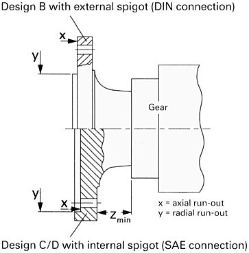
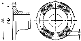
flanges Generally cardan shafts are connected to the units by companion flanges. The companion flange material must have an interfacial pressure of min. 700 N/mm˛. For standards of frictional grip flanges see ISO 7646 (DIN flanges), ISO 7647 (SAE flanges) and positive connection flanges with 70° cross-Serration ISO 8667 (XS flanges). The accurate running of a cardan shaft requires certain tolerances for the axial and radial run-out (see by DIN-flanges ISO 7646, by SAE-flanges ISO 7647 and by XS-flanges ISO 8667). x = axial run-out y = radial run-out  The dimensions of the companion flanges correspond with those of the same size of cardan shafts, except for the centering depth FA and the fit CA, and can be taken from the tables in the catalogues or from the following tables. For better bolt locking we recommend designing the recessed diameter of the companion flange as a bolt head Iocation and inserting the bolts from the companion flange side. In this case an adequate distance Zmin must be maintained between the flange and the adjacent unit. Zmin = bolt length (incl. bolt head). If it is not possible to insert the bolts from the companion flange side, the bolts can he inserted from the joint side, except for some sizes. Make sure that the nuts can be easily tightened on the companion flange side. If necessary, use companion flanges with pre-assembled bolts. Design A - Connection with staggered teeth according to ISO 8667 
(1) Number of
bolt holes per flange
(1) Number of
bolt holes per flange
(1) Number of
bolt holes per flange |
|||||||||||||||||||||||||||||||||||||||||||||||||||||||||||||||||||||||||||||||||||||||||||||||||||||||||||||||||||||||||||||||||||||||||||||
| tt back to Table of contents | |||||||||||||||||||||||||||||||||||||||||||||||||||||||||||||||||||||||||||||||||||||||||||||||||||||||||||||||||||||||||||||||||||||||||||||
| Email : info@landmark-autoparts.com | Websites |
|